The Story
Do you ever get tired of walking? Is running with a backpack too difficult? Worried about someone stealing your bicycle tires? Same. An electric board (e-board) on wheels is one of the most fun, efficient, and convienent ways to get around campus.
This whole project started when the team I work with for FSAE wanted to build our own battery modules, battery monitoring system (BMS), motor controllers. It’s quite hard to develope a full scale system so we decided to start small and integration testing is one of the easiest ways to validate a complex electromechanical system, thus, we decided to make the greatestt e-board our campus has ever seeen.
The Project
This project could be very simple. There exist many kits and modules to turn any board electric. But I’m an engineer and a problem solver. There’s nothing to do if I just buy a kit. So, I had to make some problems:
- Deck (standard skate deck, also can be considered the user interface)
- Power Plant (motors encased in custom urethane molds)
- Power Supply (battery modules)
- Power Management (BMS)
- Remote for User Control (wireless comms)
- Control Architecture (motor controllers and torque vectoring)
The Design
** I haven’t finished this project yet, but I’ll update this as I progress. **
Deck (Carbon Fiber)
A deck is the top portion of a board that a user stands on. This is the interface between the dynamic system and the user. It’s important to have flexibility for stability, as it acts like a form of suspension. It is also critical to be durable. Curbs are a real hazard for decks. Last, and most important of all, it has to be strong enough to handle numerous combined loading cases and dynamics.
The industry standard for decks is maple plywood or polymer. Not much fun in engineering maple ply that’s been tried and true, and I can’t afford the tooling for decent injection molds; so what should my deck be made of? The only cool answer to that is carbon fiber.
Carbon fiber is an engineered material. It’s pretty sweet despite its cost. On average it has four times the strength-to-weight ratio of steel. The only problem is its not isotropic like its steel counter part.
I started with some simple hand calcs on an approximate flat plate in simply supported bending using the specs for 7071 T6 aluminum. This showed promising results of an ultra light deck.
I moved on to verify my hand calcs in ANSYS using 12k 2x2 twill fabric and Sika ProInfusion resin. A full core deck is not ideal because it makes weak edges (susceptible to curb damage), increases fabrication time, and takes up valuable volume. So I played with several different core models. The best was 3.75 x 1.25 x 60 [cm] closed cell PVC foam core. Two long narrow strips runing along the truck edges to increase the second moment of area. The analysis showed that 2 layers (0 PW | 45 PW) of 12k would be sufficient (I know what you’re thinking, “no way” and you’re absolutely right. More on this later).
I went to the composites facility and began construction of a master mold because even I know my calcs are not perfect and I’m going to need to make more than one deck. After the first prototype board came out, it was time to validate the calculations… but first I took it for a ride. As soon as I loaded the tail, it snapped in two like a twig. The deck between the trucks held just fine though. I rode around for several minutes and all seemed well. Then I decided to run it through it’s paces. I took it off a standard 6” curb and the deck snapped in two.
Obviously, two layers was not sufficient. I consulted my friend who works for ANSYS and talked about simulating a more correct shape (normal decks have a dish to them to allow for more board flex and for more grip). We concluded that that would be significantly more complicated than just increasing the safety factor for a flat plate.
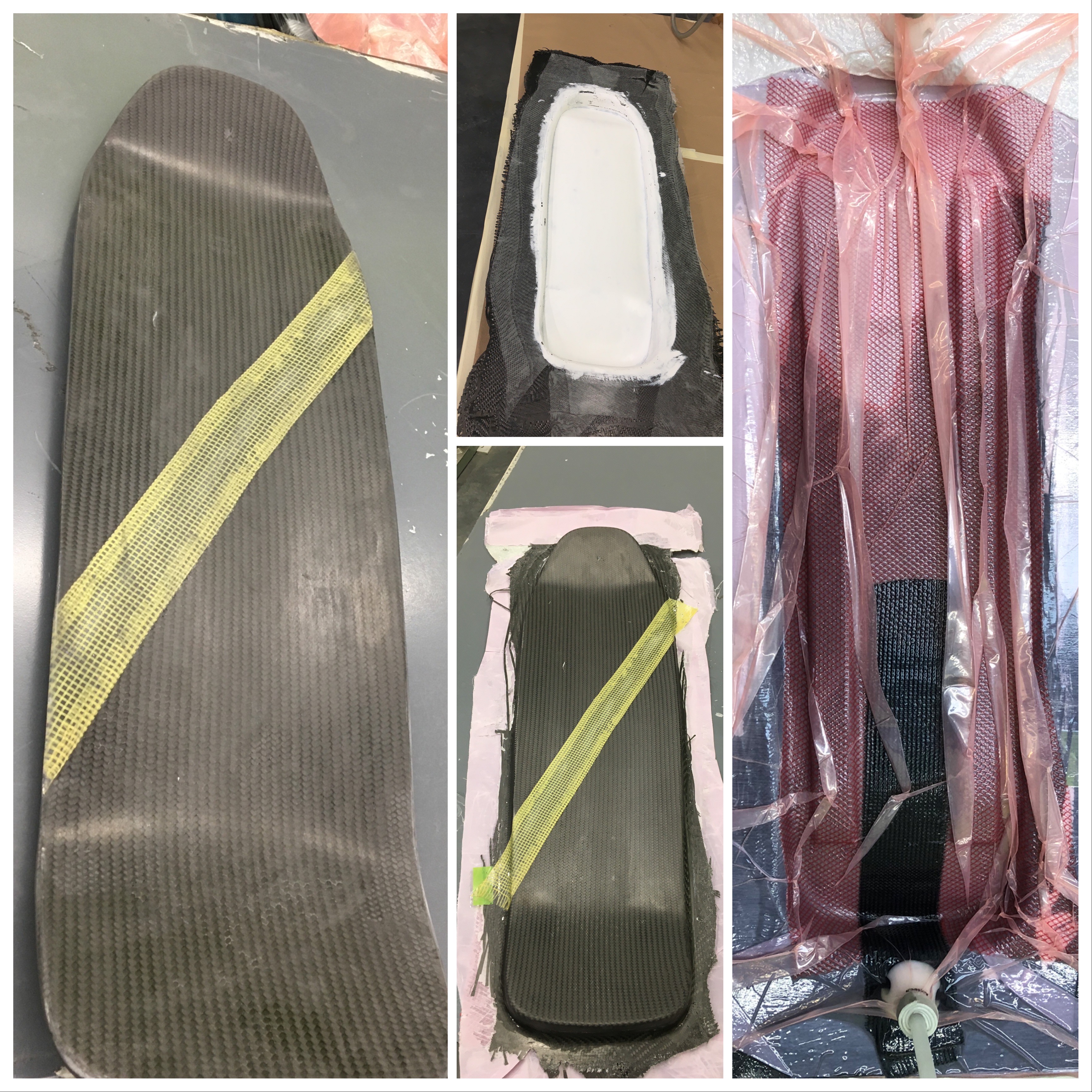
After several iterations, the final layup was (45 PW | 0 PW | 0 PW | 0 PW | 0 PW | 45 PW) for the entire deck, where the second and fifth layers were 3k 2x2 twill. The trucks were reinforce with 3 more plies of 12k and the tail was reinforced by two more layers of 12k. This design (see figure) held up to experimental testing for dynamic combined loading and the four-point bend test in an Instron machine.
Power Plant (BLDC Motors)
Power plant design is important in an application such as this where weight, size, power, and robustness are cruicial.
Things to consider:
- Reduction ratio (gear box or N) determines efficiency and all motor specs
- Voltage rating (/V_max) determines position of torque-speed curve
- Torque-Speed Curve (/k_t and /k_e) determines maximum traversable incline and velocity
- Motor Inertia (J) determines the resistance seen by the user when manually pushing
- BLDC vs PMSM determines back EMF, control architecture, and durability
After several model variations in SOLIDWORKS, dynamic simulations in MATLAB, it was determined that a gear box was not necessary if a low enought k_v (note: k_v = k_e = k_t if all are in SI units) motor can be found.